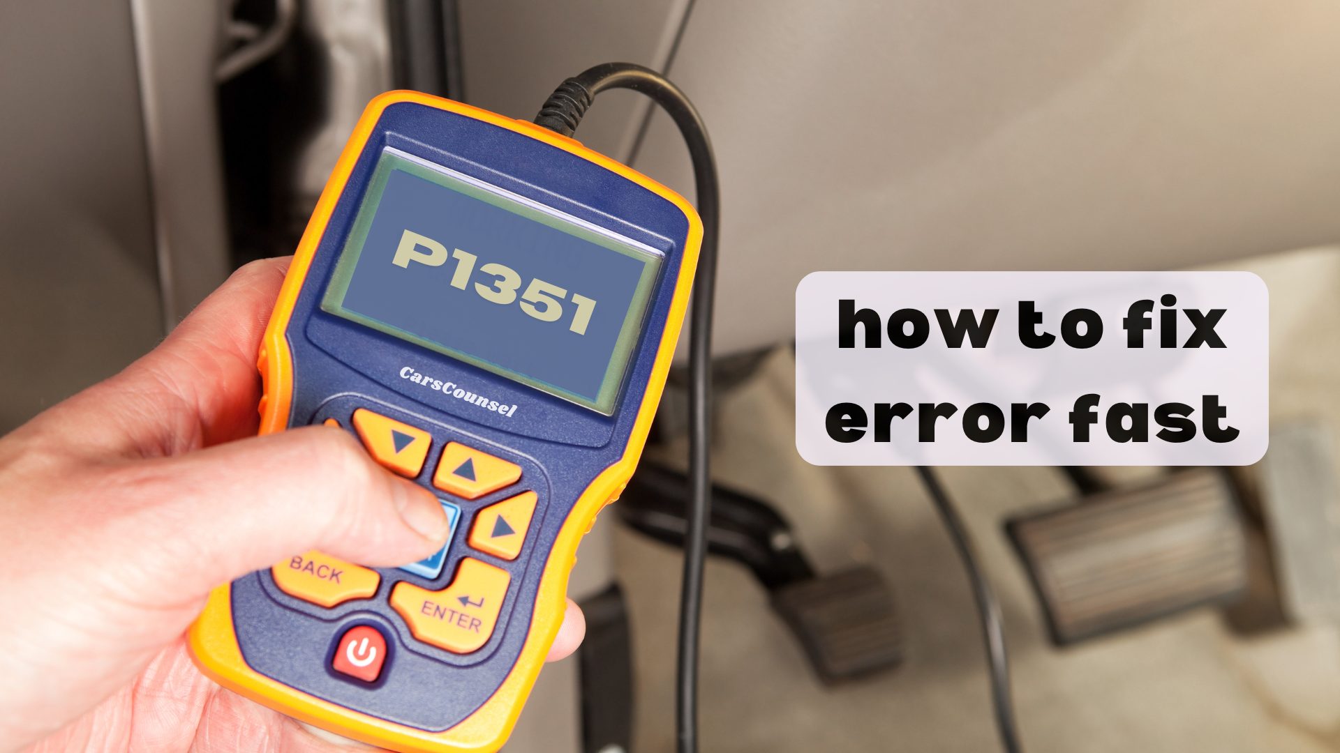
P1351 is a manufacturer-specific OBD-II diagnostic trouble code. Its exact definition depends on the vehicle application, commonly indicating an ignition coil control circuit fault or a glow plug relay issue.
This code identifies an electrical circuit condition rather than confirming a single failed component. The underlying cause requires targeted electrical diagnosis based on the exact factory definition.
Quick Navigation
Key Takeaways
- P1351 is a manufacturer-specific code, often indicating an ignition control circuit high voltage fault on GM vehicles or a glow plug relay fault on PSA vehicles.
- Possible causes include a failed ignition control module, damaged wiring, a faulty crankshaft position sensor, or a bad glow plug relay.
- Diagnosis requires verifying the exact factory definition, inspecting the relevant ignition or pre-heat circuits, and testing module operation.
- Repairs depend on the confirmed root cause and may involve wiring repair, sensor replacement, or module replacement.
P1351 Code Description and Implications
P1351 is a manufacturer-specific code, meaning its exact definition and diagnostic procedures depend heavily on the vehicle application.
Some General Motors applications: P1351 indicates an Ignition Coil Control Circuit High Voltage or Ignition Diagnostic Monitor (IDM) circuit fault. The powertrain control module detects an unexpected voltage in the ignition control circuit.
Certain Ford applications: P1351 relates to the Ignition Diagnostic Monitor (IDM) duty cycle or circuit input being out of range or high.
Some PSA Group (Peugeot/Citroën) applications: P1351 indicates a fault in the glow plug pre-heating relay control circuit, such as an open circuit or short to voltage.
Because it is manufacturer-specific, generic diagnostic paths cannot account for the unique systems monitored by different automakers. When diagnosing an OBD2 code, verifying the exact factory definition is the most critical first step.
Common Causes of the P1351 Code
The underlying causes for a P1351 code vary significantly by application and monitored system.
Failed Ignition Control Module or Coil: On GM and Ford applications, the internal driver in the ignition control module or the ignition coil itself may fail, causing a high voltage or open circuit condition.
Wiring and Connector Issues: Damaged wiring, chafed insulation, or corroded connectors in the ignition control circuit or glow plug relay circuit can interrupt the signal or cause a short to voltage.
Faulty Crankshaft Position Sensor: On some ignition systems, a failing crankshaft position sensor can disrupt the timing signal, triggering an ignition monitor fault.
Failed Glow Plug Relay: On diesel PSA applications, the pre-heating relay itself may fail internally or suffer from corroded control pins.
Symptoms Associated With P1351
The prominent symptom is the illumination of the Check Engine Light.
On gasoline applications with an ignition control circuit fault, the engine may experience severe misfires, rough idling, hesitation during acceleration, or a failure to start.
On diesel applications with a glow plug relay fault, the engine may be difficult to start in cold weather, produce excessive white smoke on startup, or run roughly until warm.
Depending on the manufacturer’s fail-safe strategies, the vehicle may enter a limp mode to protect the catalytic converter from unburned fuel.
Diagnosing the P1351 Trouble Code
Diagnosis must begin by confirming the exact factory service information for the vehicle’s specific make, model, and engine.
For GM and Ford ignition circuit applications, use a digital multimeter to test the ignition control module wiring for shorts to voltage or opens. Verify the crankshaft position sensor signal.
For PSA glow plug relay applications, check the relay control circuit for proper power and ground, and test the relay coil resistance.
Use a scan tool capable of displaying live data to monitor ignition timing advance, misfire counters, or glow relay command states.
If the external wiring and sensors test correctly, the fault may lie within the ignition control module, the PCM, or the relay itself.
Repairing the P1351 Issue
Repairs must follow confirmed diagnosis. Never replace ignition or pre-heat components solely based on the presence of the code.
If external wiring damage or connector corrosion is found, repair the harness and secure the connections before re-evaluating the system.
If electrical testing confirms the ignition control module, ignition coil, or crankshaft position sensor has failed, replace the component using a part meeting the correct vehicle specification.
On diesel applications, if the glow plug relay fails testing, replace the relay and clear the codes.
If all external circuits test correctly, follow the manufacturer’s diagnostic procedure to evaluate the PCM.
Cost Considerations for P1351 Repairs
Repair costs vary considerably depending on the confirmed root cause and the specific vehicle application.
Replacing a glow plug relay or crankshaft position sensor involves minimal to moderate parts costs and standard labor.
Replacing an ignition control module or diagnosing complex PCM wiring faults involves moderate parts and labor costs.
Cost depends on diagnostic time, component accessibility, required parts, programming requirements, and labor.
Prevention Strategies for Future Occurrences
Preventing P1351 codes requires attention to the vehicle’s electrical system and ignition components.
Inspecting exposed ignition wiring and sensor connectors for heat damage or moisture intrusion can help identify developing electrical issues before they cause an open or shorted circuit.
Keeping the engine bay clean and ensuring dielectric grease is used on sensitive electrical connectors can reduce corrosion-related faults.
Troubleshooting Tips and Best Practices
Always check for Technical Service Bulletins related to P1351 for your specific vehicle application.
Manufacturers may release updated ignition control modules, revised wiring harness pigtails, or software updates to address known circuit faults.
Do not assume the entire ignition system requires replacement simply because a monitor circuit code is present.
A simple broken wire, a corroded connector pin, or a bad ground can produce the P1351 code without the primary ignition components being defective.
If the vehicle recently underwent timing or ignition work, verify that all sensor connectors were fully seated and no pins were pushed out.
More OBD-II Codes
| P1350 | P1349 | P1348 | P1347 |
| P1346 | P1344 | P1352 | P1353 |
| P1354 | P1355 | P1356 | P1357 |
| P1361 | P1362 | P1300 | P1310 |
| P1336 | P1380 | P0300 | P0301 |
| P0302 | P0303 | P0304 | P0335 |
Frequently Asked Questions
Is the P1351 code generic or manufacturer-specific?
No. P1351 is a manufacturer-specific code. Its exact definition depends on the vehicle application, commonly indicating an ignition control circuit fault on GM or a glow plug relay fault on PSA.
Can a bad crankshaft position sensor cause a P1351 code?
Yes, on some GM and Ford applications. The crankshaft position sensor provides the timing signal for the ignition system. If it fails, it can disrupt the ignition diagnostic monitor circuit and trigger the code.
Will disconnecting the battery clear the P1351 code?
Disconnecting the battery may temporarily clear the code, but it does not repair the underlying electrical fault. It also erases valuable freeze frame data and resets readiness monitors, complicating professional diagnosis.
Can I drive my vehicle with a P1351 code?
Driving is not recommended. An ignition control circuit fault can cause severe misfires, stalling, or a no-start condition. Continued driving with misfires can also overheat and damage the catalytic converter.
Does P1351 mean the ignition control module must be replaced?
Not necessarily. While a failed module is a possible cause, damaged wiring, corroded connectors, or a faulty crankshaft position sensor can also interrupt the circuit. The wiring and sensors must be tested first.
What Should You Do About the P1351 Code?
Confirm the exact factory definition and diagnostic procedure for your specific vehicle application before attempting repairs.
Do not assume the ignition control module or glow plug relay requires replacement based solely on the presence of the diagnostic trouble code.
Inspect the external wiring and connectors, verify the relevant circuit resistance and signals, and review live data to rule out external electrical faults.
Follow the applicable manufacturer diagnostic workflow to isolate the relevant system and components before replacing any hardware.